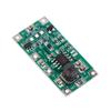
TPS61088 5/9/12V High Power Li-ion Battery Boost DC-DC Power Module 10A Current 1MHz Frequency
Barva
Jako na obrázku


Vlastnosti
Popis
Hign-concerned Chemical : None Model Number : 123 Type : Voltage Regulator
Origin : China Condition : New
This module uses TI TPS61088 power chip programme, stable performance, small ripple, with a 10A switching current capability, switching frequency of about 1MHZ, the module provides PWM and PFM two modes of operation user-adjustable (the default PFM low-power mode shipment), on-board high-quality tantalum capacitors (adjustable version) as well as high-current inductors, the use of high-quality components to further improve the module performance and stability.
Module in the output of high-power occasions still have most of the other boost module can not be comparable to the stability of the user in the use of multiple lithium batteries in parallel power supply boost applications to 5V voltage 4A/5A output of high-current occasions are a good choice, the same boost to 9V/12V voltage is not a problem, the output power Highest can be up to 30W, 9V, 12V output, the larger current occasions output, the user will not have to pay attention to the power consumption of the module, the user will be able to use the module in a more efficient way. The output power can be up to 30W with 9V and 12V voltage output, and the user only needs to do a good job of heat dissipation to get a good output ripple with load when outputting a large current.
If not specified, the following parameters are tested in PWM mode (recommended operating mode). Module Type: Switching Power Supply, Boost Power Supply
Input Voltage:DC2.7-12V
Input current:9A(max)
Output current:Determined by the input, refer to the following instructions for calculation
Output Voltage:DC4.5-12.6V
Output power: 30W(max), heat dissipation measures required
Switching frequency: about 1MHZ
Operating mode: PWM /PFM
The following parameters are measured when the boost value is adjusted to 9V in PWM mode, for user's reference Quiescent current:15-65ma(PWM mode)
200ua-600ua(PFM mode)
Output ripple:30mVpp(no load)
Output efficiency:92%(max)
Adjustment mode: potentiometer, counterclockwise boosting
Jumper pad selection, 5/9/12V, ADJ pad can be adjusted by yourself
Module interface:KF301-5.08/pads
Module weight:10g/5.4g
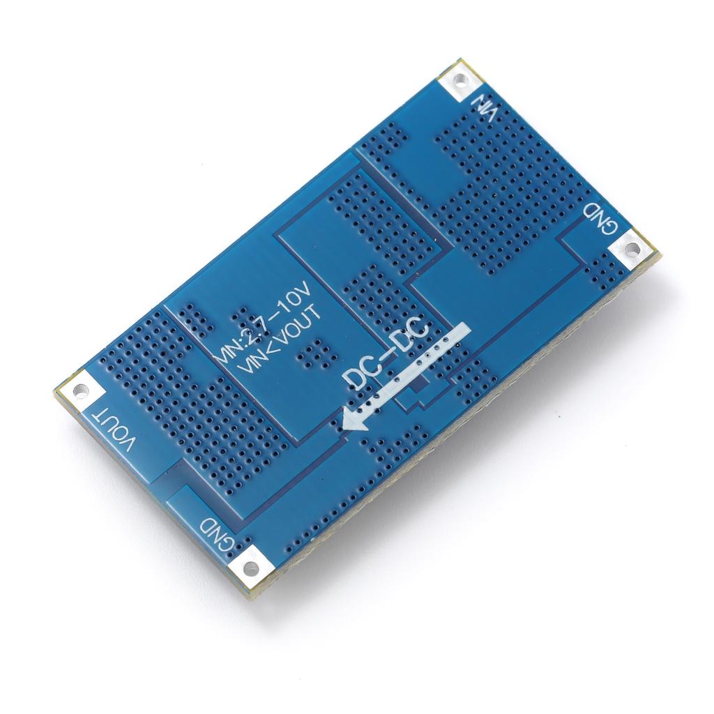
Module size: 40x22mm (manual measurement, there are deviations) VIN:Power input positive, 2.7-12V
GND:Input and output negative terminal, common
VOUT: Power output positive, 4.5-12.6V
Jumper pads: short to enable the corresponding voltage, if all the jumper pads are not shorted, then use the ADJ resistor to adjust the voltage, the three discs and the ADJ resistor can only choose one way to work PWM shorting pad on the side of the output terminal is shorted for PWM mode, and disconnected for PFM mode, default is PFM mode, users can adjust it by themselves. For the fixed voltage version, the default is PFM mode, can be adjusted to PWM mode by soldering a 0Q resistor to the PNIM pads or shorting the two pads in other ways. 1. The module is a boost module, so the output voltage of the module needs to be larger than the input voltage, after testing, it is recommended that the output voltage is higher than the input voltage by more than 2V, otherwise it is easy for the output voltage to be higher than the set value.
2. The module MAX switching current is 10A, users are required to leave room for use within 9A.
3. Output current is determined by the input parameters, the input current shall not exceed 9A, the efficiency of 70% (leave a margin) for the calculation, to get the following formula for calculating the module output MAX current value: lout = Vin * 6.3 / Vout.
4. Module in the input voltage is too low when the output power can not be fully played out, in the following 3V power supply is particularly obvious, the demand for larger power output users need to pay attention to when used
1, please do not touch the bottom potentiometer pin area with your hands or other substances with small resistance value, the contact will be a change in the potential resistance value and lead to large fluctuations in the output voltage.
2、Please use a shorter/thicker wire to connect when measuring voltage with larger current load (wire resistance will affect the measured voltage), or measure directly to the terminals, otherwise it will lead to inaccurate voltage measurement.
3, the above parameters are not module limit values, but to leave some room after the parameters specified in the module test its output power in the case of cooling fins for heat dissipation long run over 50W This shows that in high-power occasions a good thermal environment is particularly important.
4, on the use of EN port, EN port default connection to VIN, for the boost mode on, EN connected to GND for the shutdown mode, users need to note that the shutdown mode does not mean that no output, but the chip boost function will be shut down, at this time the output voltage will be slightly lower than the input, and can output current.
5, in order to avoid customers touching the module circuitry due to static electricity and other reasons leading to chip burnout, so should try to avoid the module in the power-up with hands touching the chip near the circuit.
The line layout is compact and regular, with good electrical insulation and mechanical stability, and can maintain stable performance under different temperature and humidity environments to ensure accuracy and reliability.
In circuit design, carefully planned lines are like precision transportation networks, and lines of different widths and spacings undertake different currents and signals transmission tasks respectively. The key signal lines are impedance matching processing, which greatly reduces signal reflection and attenuation and ensures the stable transmission of high-frequency signals.
All kinds of electronic components are soldered on the circuit board, and the solder joints are full, round, and firm and reliable. Core components like chips are perfectly connected to the circuit board through fine packaging processes to achieve high-speed data processing and interaction.
This circuit board has a wide range of responses in many fields. Whether in the industrial control field that requires extremely high stability or consumer electronics field that pursues extreme performance, it can provide solid guarantees for the stable operation of the equipment with its excellent design and reliable performance, and help various electronic devices play a powerful role.