Hign-concerned Chemical : None
Package : DIP
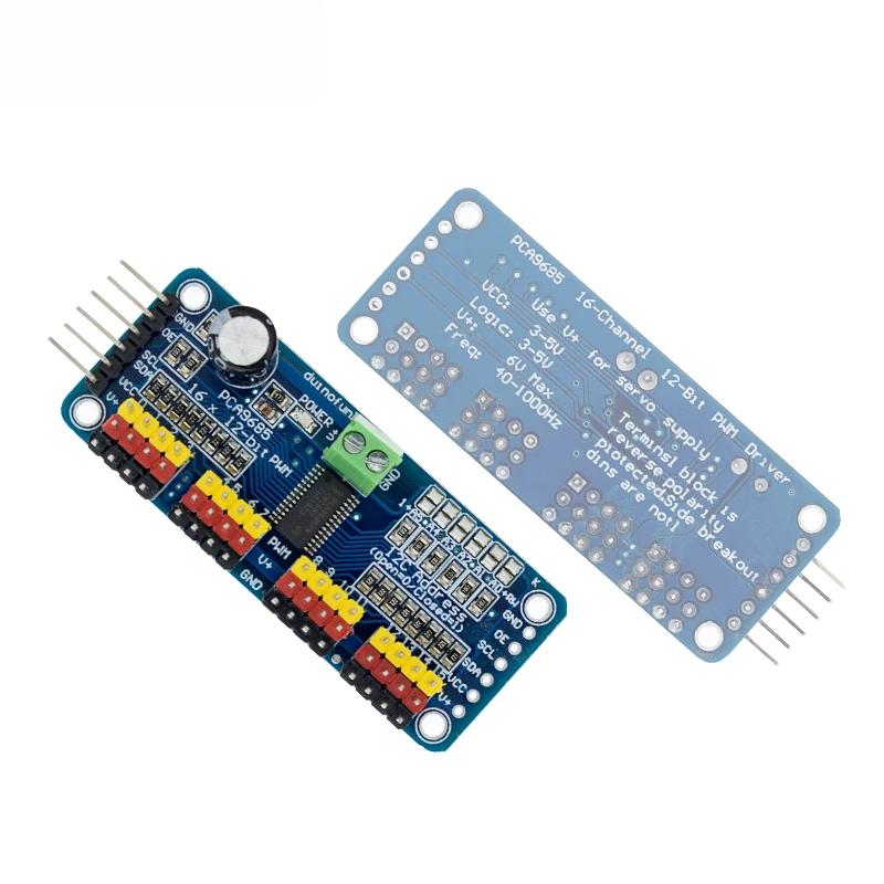
Model Number : PCA9685 16 Channel
Dissipation Power : 1
Supply Voltage : 1
Application : Computer
Type : Voltage Regulator
Origin : China
Condition : New
Operating Temperature : -40-85+
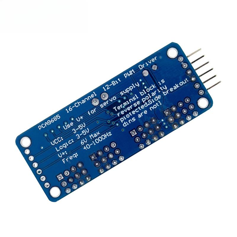
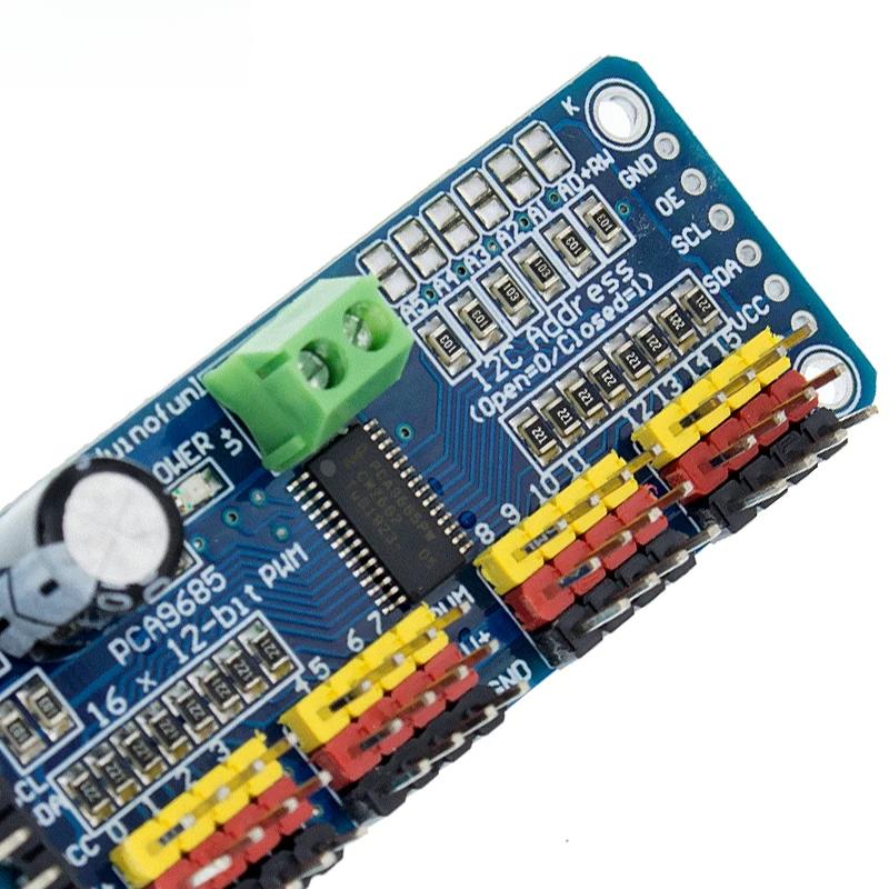
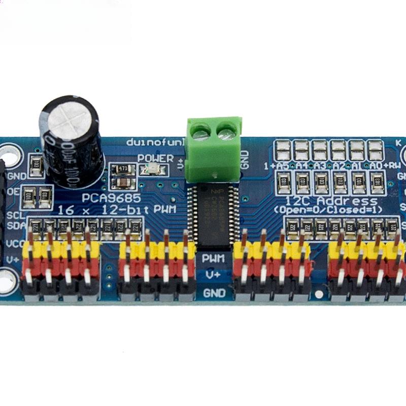
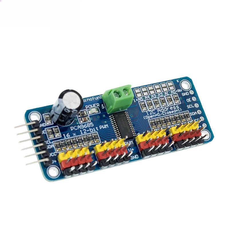
Description:Want to make a hexapod walker? Maybe you're making a piece of art with tons of moving parts, or you need to drive a ton of LEDs with precise PWM output. Your microcontroller has a limited number of PWM outputs, and you find yourself running out! Not with the Adafruit 16-Channel 12-bit PWM/Servo Driver - I2C interface. With this pwm and servo driver breakout, you can control 16 free-running PWM outputs with just two pins! Need to run more than 16 PWM outputs? No problem. Chain together up to 62 of these beauties for up to an outstanding 992 PWM outputs.Features:Dimensions (no headers or terminal block) 2.5" x 1" x 0.1" (62.5mm x 25.4mm x 3mm)Weight (no headers or terminal block): 5.5gramsWeight (with 3x4 headers & terminal block): 9gramsThis board/chip uses I2C 7-bit address between 0x60-0x80, selectable with jumpersTerminal block for power input (or you can use the 0.1" breakouts on the side)Reverse polarity protection on the terminal block inputGreen power-good LED3 pin connectors in groups of 4 so you can plug in 16 servos at once (Servo plugs are slightly wider than 0.1" so you can only stack 4 next to each other on 0.1" header"Chain-able" designA spot to place a big capacitor on the V+ line (in case you need it)220 ohm series resistors on all the output lines to protect them, and to make driving LEDs trivialSolder jumpers for the 6 address select pinsi2c-controlled PWM driver with a built in clock. Unlike the TLC5940 family, you do not need to continuously send it signal tying up your microcontroller, its completely free running!It is 5V compliant, which means you can control it from a 3.3V microcontroller and still safely drive up to 6V outputs (this is good for when you want to control white or blue LEDs with 3.4+ forward voltages)6 address select pins so you can wire up to 62 of these on a single i2c bus, a total of 992 outputs - that's a lot of servos or LEDsAdjustable frequency PWM up to about 1.6 KHz12-bit resolution for each output - for servos, that means about 4us resolution at 60Hz update rateConfigurable push-pull or open-drain outputOutput enable pin to quickly disable all the outputs(1)Drive board connected to Arduino:The PWM driver board uses the I2C method, so only four lines can be connected to the Arduino device:"Classic" Arduino pin mode:+ 5v -> VCCGND -> GNDAnalog 4 -> SDAAnalog 5 -> SCLOld Mega pin way:+ 5v -> VCCGND -> GNDDigital 20 -> SDADigital 21 -> SCLR3 and later Arduino pin method (Uno, Mega &Leonardo):(These boards have dedicated SDA and SCL pins)+ 5v -> VCCGND -> GNDSDA -> SDASCL -> SCLVCC pin is only for the chip power supply, if you want to connect the servo or LED lights, use the V + pin power supply, V + pin supports 3.3 ~ 6V power supply (chip safe voltage 5V). It is recommended to connect the external power supply via the power supply terminal.(2) power supply part:Most of the servo design voltage is 5 ~ 6V, especially in a number of steering gear at the same time running, with the need for high-power power supply. If you are directly using the Arduino 5V pin to power the servo directly, there are some unpredictable problems, so we recommend that you have a suitable external power supply for the drive board.(3) Connect the servo:Most servos are connected using standard 3-wire female plugs, as long as the corresponding pin into the driver board on it. (Ground wire is generally black or brown, the signal line is generally yellow or white)(4) for the driver board assigned address:Each drive board of the cascade needs to have a unique access address. The initial I2C address of each driver board is 0 × 40, you can modify the upper right corner of the jumper I2C address. Connect a jumper with solder to indicate a binary number "1".
The line layout is compact and regular, with good electrical insulation and mechanical stability, and can maintain stable performance under different temperature and humidity environments to ensure accuracy and reliability.
In circuit design, carefully planned lines are like precision transportation networks, and lines of different widths and spacings undertake different currents and signals transmission tasks respectively. The key signal lines are impedance matching processing, which greatly reduces signal reflection and attenuation and ensures the stable transmission of high-frequency signals.
All kinds of electronic components are soldered on the circuit board, and the solder joints are full, round, and firm and reliable. Core components like chips are perfectly connected to the circuit board through fine packaging processes to achieve high-speed data processing and interaction.
This circuit board has a wide range of responses in many fields. Whether in the industrial control field that requires extremely high stability or consumer electronics field that pursues extreme performance, it can provide solid guarantees for the stable operation of the equipment with its excellent design and reliable performance, and help various electronic devices play a powerful role.