Hign-concerned Chemical : None
Package : DIY Module
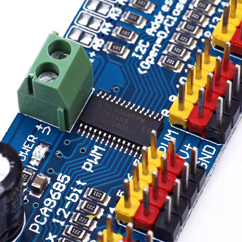
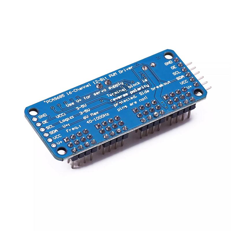
Model Number : PCA9685
Dissipation Power : ...
Supply Voltage : 3.3V-5V
Application : Computer
Type : Module
Operating Temperature : -40℃~+80℃
Origin : China
Condition : New
Functions : Electronic Module
Range of application : Switch And Sensor For Arduino STM
You want to make a cool robot, maybe a six-legged walking robot, or just a piece of art with lots of moving parts. You may also want to drive many LED indicators with a precise PWM output. Then you realize that your microcontroller has a limited number of PWM outputs! So what are we going to do? You can give up or you can use this handy PWM servo drive small board.
■ It is an i2c communication with a built-in PWM driver and a clock. This means that it will be very different from the TLC5940 series. You don't need to keep sending signals to occupy your microcontroller!
■ It is 5V compatible, which means you can also use 3.3V MCU control and safely drive to 6V output (3.4+ positive voltage is also possible when you want to control white or blue indicators)
■16 address selection pins enable you to hook 62 driver boards to a single i2c bus, with a total of 992 PWM outputs. That would be a huge resource.
■ Approx. 1.6Khz PWM output
■ Prepare the output 12-bit resolution for the stepper motor, which means that 4us resolution can be achieved at an update rate of 60Hz
■ Configurable push-pull output or open circuit output
■ Output Enable pins quickly disable all outputs
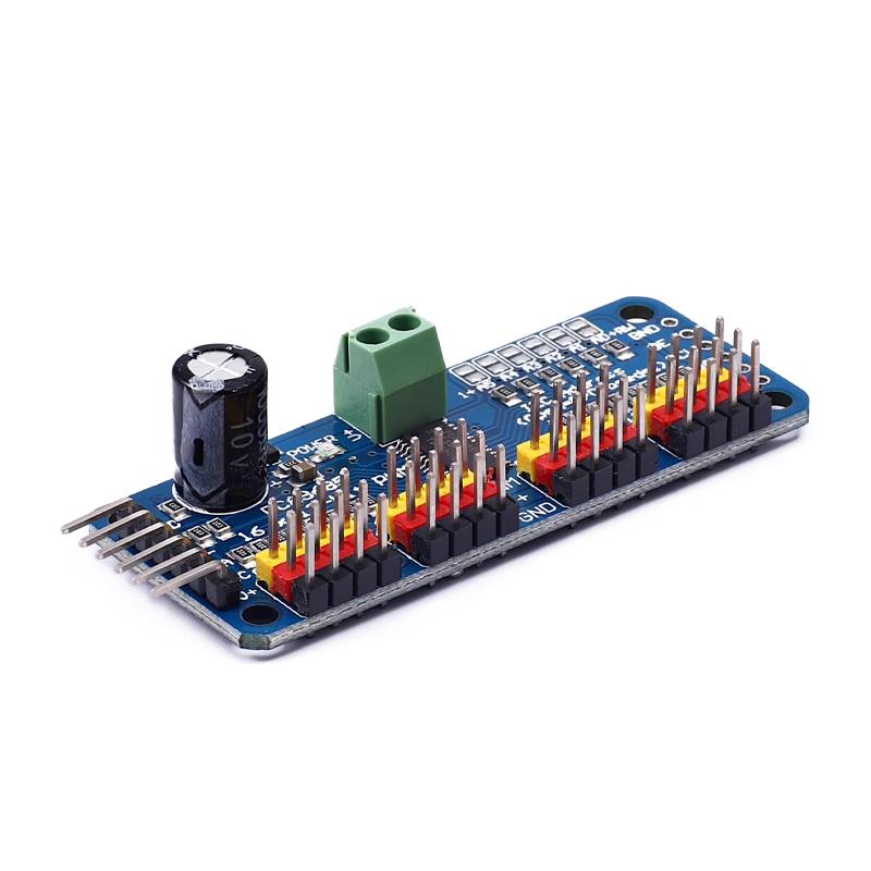
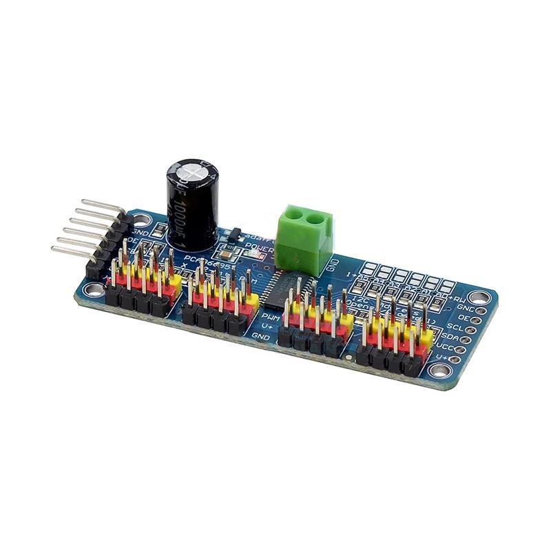
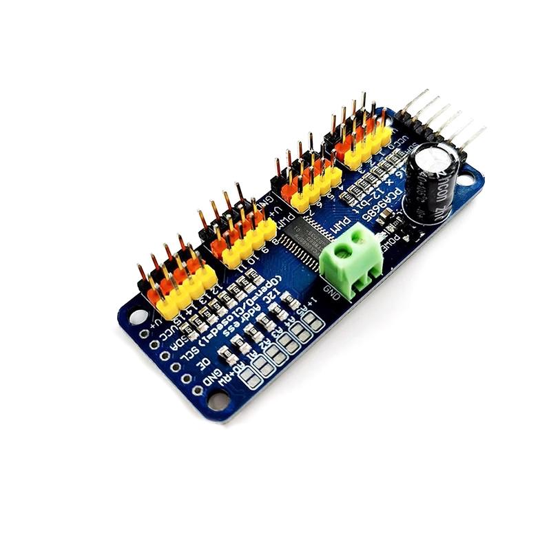
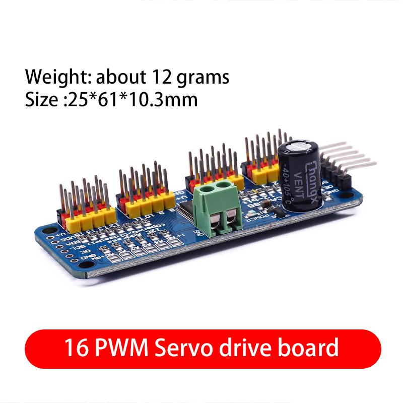
● The PCA9685 chip is wrapped in the center of the small board
● Power input terminal
● Green power indicator
● Easy to insert 16 servomotors at once in 4 sets of 3-pin connectors (the plugs of the servomotors are slightly wider than 0.1", so you can put 4 pairs of 0.1" connectors)
● Reverse polarity protection for input on the patch board
● Cascade design
● Place a large capacitor on the V+ line (in some cases you will need) the maximum voltage of the peripheral input depends on this 10V1000uf capacitor
● Put a 220 ohm series resistor on all PWM output lines to protect them and drive the LED easily.
The line layout is compact and regular, with good electrical insulation and mechanical stability, and can maintain stable performance under different temperature and humidity environments to ensure accuracy and reliability.
In circuit design, carefully planned lines are like precision transportation networks, and lines of different widths and spacings undertake different currents and signals transmission tasks respectively. The key signal lines are impedance matching processing, which greatly reduces signal reflection and attenuation and ensures the stable transmission of high-frequency signals.
All kinds of electronic components are soldered on the circuit board, and the solder joints are full, round, and firm and reliable. Core components like chips are perfectly connected to the circuit board through fine packaging processes to achieve high-speed data processing and interaction.
This circuit board has a wide range of responses in many fields. Whether in the industrial control field that requires extremely high stability or consumer electronics field that pursues extreme performance, it can provide solid guarantees for the stable operation of the equipment with its excellent design and reliable performance, and help various electronic devices play a powerful role.